
INTRODUCTION
The Sharp family of infrared range finders are used extensively for robotics and automatic distance measurement applications. Unfortunately, the output of these sensors are inherently non-linear. In other words, a big change in output voltage does not always indicate a big change in distance to an object. In order to get distance values in common units (e.g. inches or centimeters), a user must derive a function to convert the sensor output voltage into a distance value.
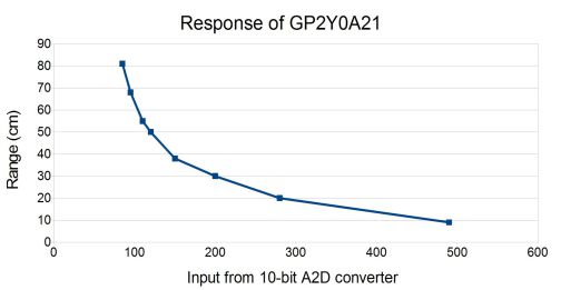
Figure 1: Example range distance vs GP2Y0A21 output voltage as converted by a 10-bit A2D
One approach is to use sophisticated mathematics programs to generate a curve fit. The functions that such programs generate are quite good but usually require floating point math and a good math library in order to implement them. This isn't much help when using microcontrollers that lack floating point capabilities. In addition, such implementation are costly in compute time and power consumption.
Another approach is to use piecewise linear approximation to convert the output voltage to a range value. This involves breaking up the response into small straight lines and doing a separate approximation for each line segment. Straight line approximations are simple to compute and can be implemented with fairly good accuracy even using only integer math. The disadvantage is that they use more code space too implement. The extreme of this option is to use a full look-up table for every possible sensor output. Obviously such an implementation requires a substantial amount of program RAM and/or NVRAM.
Ideally, an the linearization would use a single approximation function which works well in integer math. Fortunately, there are some simple calculations that can linearize the response of the Sharp sensors.
THE LINEARIZING FUNCTION
According to the 'Sharp Device Specification for Distance Measuring, Sensor Model No. GP2D120', the sensor output voltage as a function of distance range to an object is approximated by the following equation:
Equation 1: Linearization of sensor output vs range
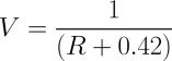
Where V is voltage and R is range, the equation produces a very straight line. The inversion (1/x) operation acts as a linearizing function to turn the ungainly curve in figure 1 into a nearly linear curve shown in figure 2. This observation is the key to finding a simple linear approximation function for the output of Sharp IR range finders.
The constant in the linearization function (equation 1) depends on the sensor type and calibration data parameters. The value of 0.42 in equation 1, works well for the GP2D120 since it is based on the calibration points in the Sharp datasheet, but may not be suitable for other sensors. As such, this constant can be represented as k since it may change for different sensors. The first step in getting a good voltage-to-range function is to find a constant k that linearizes the data. The following plot shows how the GP2Y0A21 response graph (figure 1) can be linearized by defining the variable k = 4.0.
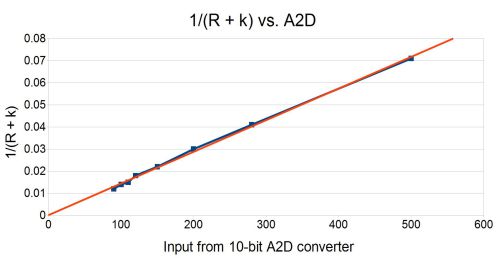
Figure 2: Linearized GP2Y0A21 Graph
The next step is to find a straight line approximation that relates the voltage to the linearizing function. This involves finding suitable m and b constants for the familiar line equation:
![]()
Equation 2: Basic line equation
In this case, y is equal to the linearized range or distance. Substituting the linearizing function from above for y and substituting V for x yields:
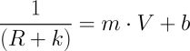
Equation 3: Line function after substitution
Rearranging the equation terms gives range as a function of voltage:
Equation 4: Solve equation 3 for range
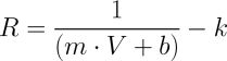
This is a useful result for languages and computing systems which support floating point math, but it can be rearranged further to get:
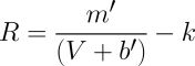
Equation 5: Simplifying for integer math
where m' = 1/m and b' = b/m . This extra step produces an equation that works nicely with integer math since the inversion of the constants are simple to pre-compute. In some cases b' will be negative, so the system must check that V is larger than b' before attempting this calculation in order to prevent a divide-by-zero error.
THE CONSTANTS
Deriving the constants in equation 5 takes a bit of up front work. The first step is to collect calibration data. This data can be obtained experimentally or "eyeballed" from the voltage-to-range curve on the spec sheet. Create a table of voltage vs. range for a set of range values. Then create a table of voltage in controller units vs. linearized range. Controller units are, for example, the output as measured by an analog to digital (A2D) converter. Some experimentation may be required to find a k constant that produces a linear plot. Computing a linear regression on the data will produce the m and b constants. This computation can easily be done in basic spreadsheet programs.
THE RESULTS
For a microcontroller using 10-bit A2D measurements, such as the USBStem, the sensor output reading will range from 0 to 1023 ((2^10)-1). As an example, interpolation yields the following formula for a GP2Y0A21 sensor:
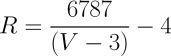
Equation 6: Linearized GP2Y0A21 range in integer math
Comparing equation 5 and 6, m'=6787, b'=3 and k=4. For equation 6, V must be greater than 3 in order to avoid a divide-by-zero error. With 10-bit integers, voltage measurements from a GP2D12 are typically above 80 when any object is in range. If nothing is in front of the sensor, the readings can drop to 0.
This approach can also work for other Sharp sensors. After plugging in "eyeballed" calibration data for a GP2D120 and adjusting the k offset to get a straight line, the following formula can be derived for a GP2D120:
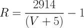
Equation 7: Linearized GP2D120 range in integer math
Due to the use of integer math, the range units output from these equations will not be exactly centimeters but these functions will provide a range measurement that is more user-friendly than just using the raw A2D reading.
SUMMARY
Approximations used in this linearization method work well for controllers which use integer math and will work even better for controllers that have floating point capabilities. Successful implementation depends on the quality of the calibration data and a good choice of the k constant to linearize the response curve for a given sensor model.
Add New Comment