USB-C Specifications: Getting Started
The Universal Serial Bus (USB) has become an essential component of modern computing, providing a standard interface for a wide range of devices. The latest iteration of USB technology, USB-C, offers several improvements over the previous generation of USB-A ports, including faster data transfer speeds, increased power delivery capabilities, and a reversible connector. Now being, one connector to rule them all, what happens when you plug in a USB-C cable or device? A key change with USB-C is the advent of a connection state machine. The state machine manages the flow of data and power between devices. This is critical since any USB-C port could play any role in the connection. We will explore how the USB-C connection state machine operates and how this differentiates USB-C from older USB-A ports.
Some terminology and the basics:
Before diving into the specifics, let's review some basic USB terminology.
USB devices are classified as a power source, sink, or dual-role. A source provides power to the connected device while acting as a host for all data transfers (Downstream Facing Port). A sink consumes power from the connected device and acts as a peripheral device (Upstream Facing Port). A dual-role port can act as either, a source or a sink, depending on the attached device.
The ability for a USB-C connector to be either power role is unique from the previous generation. USB-A ports are fixed as a power source, while USB-B ports remain a power sink. Also, because of the USB-C port's ability to be either power role, they have the option to remain disabled until there's an established connection and a known power role. The ability to detect a connection, be either power role, and have multiple connector orientations created the need for a connection state machine.
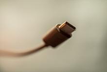
Let's go over some USB-C basics. A USB-C receptacle has two configuration channels (CC lines) used for connection negotiation. A USB-C plug has only one configuration channel for orientation and utilizes the other side, where the second configuration channel would be, for power (Vconn).
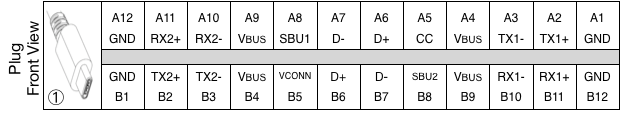
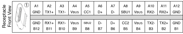
Figure 1: USB-C plug and receptacle pin-out definition.
When a device is not connected, the port remains in an unattached state. The configuration channels (CC1/CC2) are either pulled up (Rp), pulled down (Rd), or toggling between pull up and pull down depending on if it's a source, sink, or dual-role port. The lack of an opposite pull-up/down resistance indicates no device connected to the port. When a sink device is connected to a source device using a USB-C cable, the CC line through the cable is pulled low, signaling a device is attached to the port. One unique feature of USB-C is the option to not provide power until it is in an attached state. This is in contrast to USB-A ports, which always provide power. While a USB-C source is connected, it monitors the active CC line for a loss of the pull-down resistance to stop powering Vbus and transition to unattached.
Figure 2: USB-C Source and Sink CC Monitoring.
The in-depth look at the connection state
Now let's take a closer look at how the state machine operates. For a USB-C sink device, the state machine goes through several states as the device is connected and disconnected from a source device. These states include:
1. Unattached.SNK: The device is not connected to a source and is in an unattached state. The sink may be unpowered and is presenting an Rd resistance on the CC lines.
2. AttachWait.SNK: The device is attached to a source and is waiting for the source to provide Vbus (power). There will be both an Rp and Rd resistance on the CC lines.
3. Attached.SNK: The device is attached to a source and can consume power.
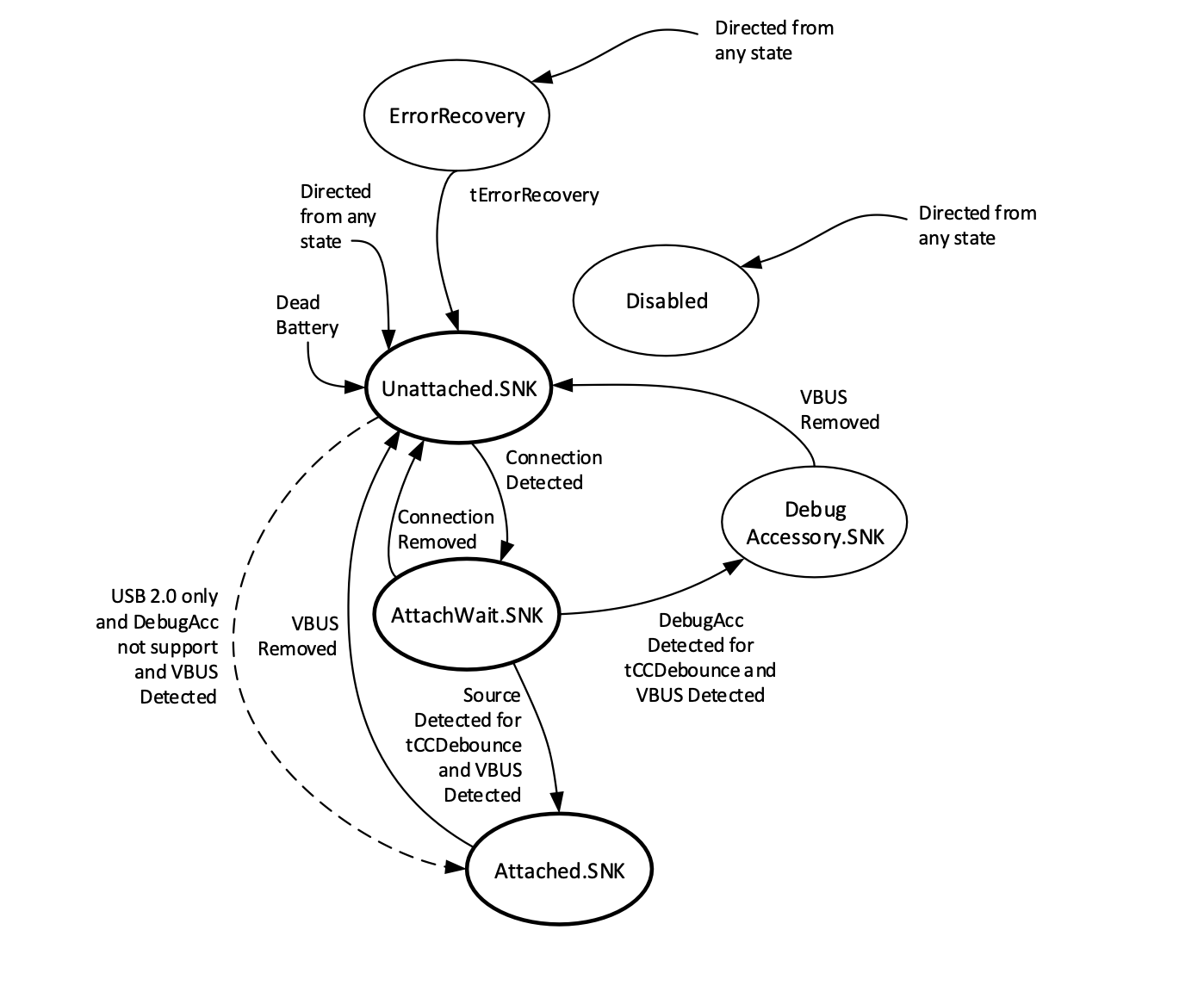
Figure 3: USB-C Sink Connection State Machine.
For a USB-C source device, the state machine goes through several states as the device is connected and disconnected from a sink device. These states include:
1. Unattached.SRC: The device is not connected to a sink and is in an unattached state. Vbus is not being provided and the appropriate Rp resistance is present on the CC lines.
2. AttachWait.SRC: The device is attached to a sink and is enabling Vbus (power).
3. Attached.SRC: The device is attached to a sink and is providing power.
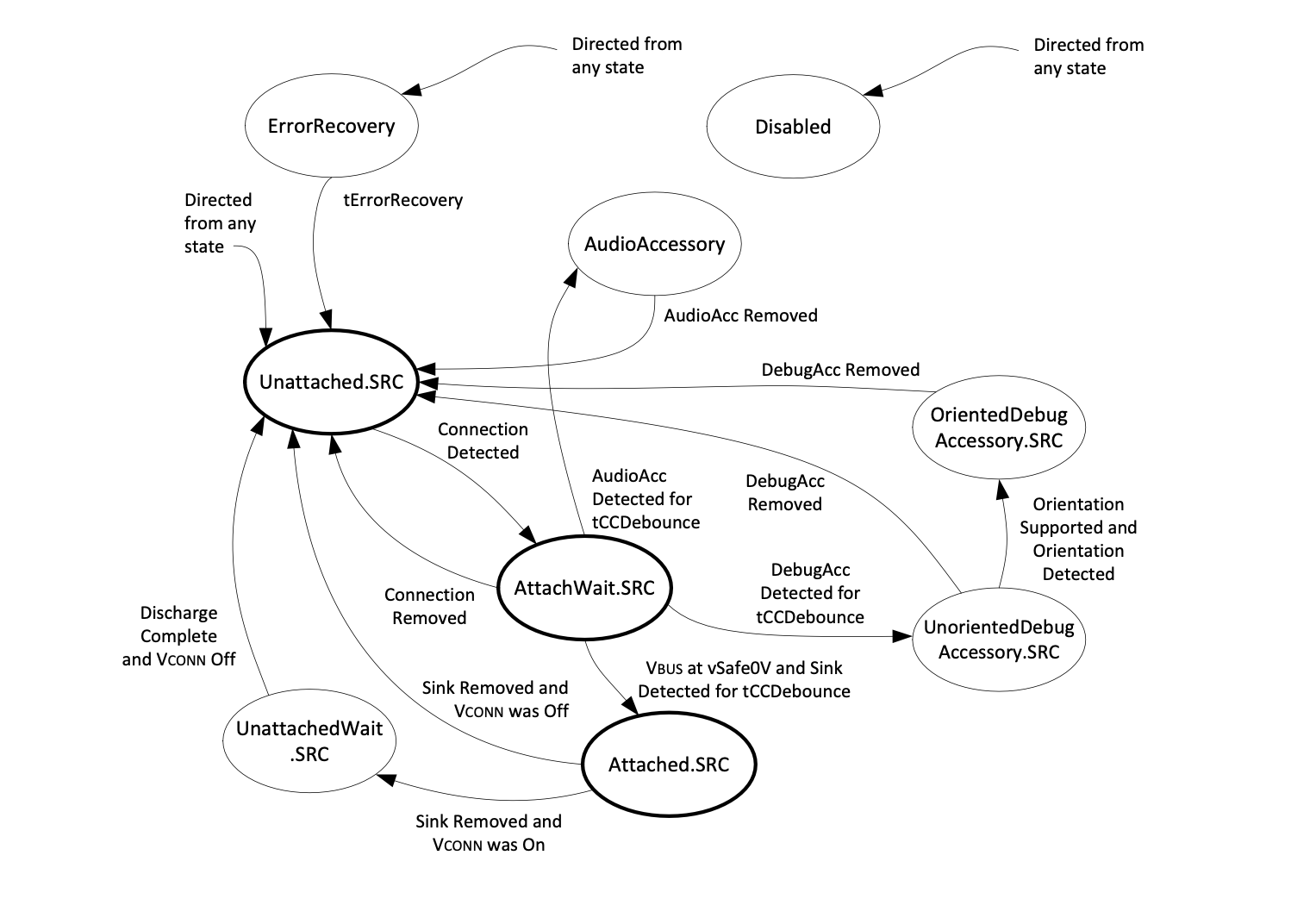
Figure 4: USB-C Source Connection State Machine.
Dual-role ports can act as either a source or a sink depending on the requirements of the connected device. The state machine for dual-role ports combines the states of both the source and sink ports. When unattached, the device will toggle between Unattached.SRC and Unattached.SNK roughly every 70 milliseconds.
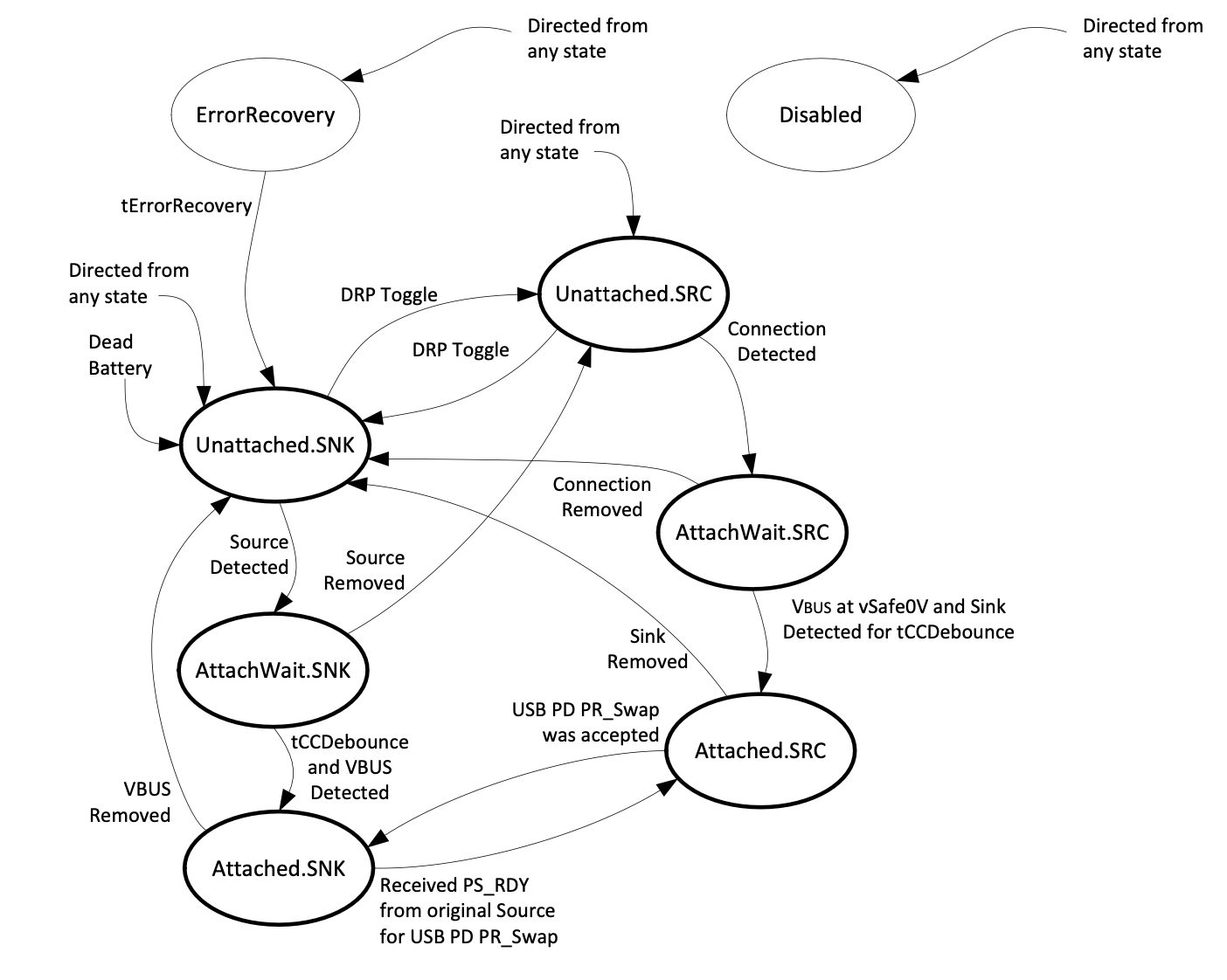
Figure 5: USB-C Dual Role Power Connection State Machine.
The USB-C connection state machine also uses the CC lines to establish the orientation of the port. For example, the source device uses a pull-up resistor (Rp) on the CC1 line, while the sink device uses a pull-down resistor (Rd) on the CC1 line, and the USB-C cable's CC orientation aligns with CC1 on both ports. They have established a connection and are oriented around CC1.
What about the USB-C cables?
Another unique aspect of USB-C is the option for electronic marker (E-Mark) chips included in USB-C cables. These chips allow for the advertisement of the cable's capabilities to the connected devices, such as max voltage/current and max data transfer speeds. E-Marks are not required and in the absence of one, a device will fall back to the safe parameters of max current of 3A, max voltage of 20V, and data rates of USB 2.0 (480Mbps) and/or USB 3.0 (5/10Gbps). All full-featured USB-C cables that can support 5A, 50V, and USB4 (40Gbps) will be E-Marked. An E-Marked cable will connect a pull-down (Ra) resistor to Vconn, the opposite of the CC line used for the device-to-device connection, which signals the source device to power Vconn with 5v. Vconn is used by E-Marks, accessories like active cables, and display adapters.
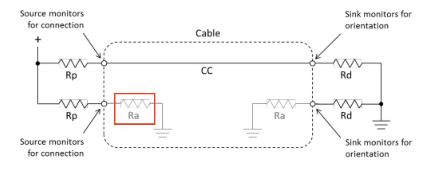
Figure 6: USB-C Cable CC Negotiation.
Conclusion
The USB-C connection state machine is a crucial component of the USB-C specification. It manages the connection, orientation, and flow of power between devices. There is much more information expanding on this subject in the way of USB Power Delivery, USB Alternate Modes, and support of legacy protocols, debug, or audio. Understanding how the state machine operates and the subtle differences between source, sink, and dual-role ports is essential for designing and developing USB-C devices. With its reversible connector, faster data transfer speeds, and increased power delivery capabilities, USB-C is the new standard for USB connectivity and has to be understood for new product development.
References
USB Power Delivery Specification R3.1 V1.7, USB-IF, (https://www.usb.org/sites/default/files/USB%20PD%20R3.1%20V1.7_0.zip)
Add new comment