PWM (Pulse Width Modulation) refers to the concept of rapidly pulsing a digital signal on a wire. Along with many other uses, it can be used to simulate a varying static voltage. PWM is commonly used for driving motors, heaters, LEDs or lights in varying intensities or speeds.
TERMINOLOGY
- Period - the time between rising edges (seconds).
- Frequency - the rate of rising edges (Hz or cycles per second): this is simply the inverse of the period
- Duty Cycle - time in the period that the pulse is active or high (percentage of the full period)
EXAMPLE ILLUSTRATION
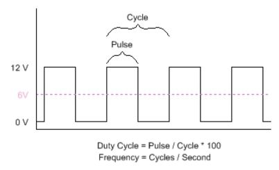
Example of a PWM signal at 50% duty cycle
In the above diagram, the duty cycle is shown at 50%. The pink line shows the average output and you can see that at 50% duty cycle, the output averages is roughly 6V or 50% of maximum voltage. Below is a diagram of what a 25% duty cycle PWM signal looks like:
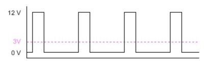
Example of a PWM signal at 25% duty cycle
AUDIBILITY
A common issue or complaint with system which utilize PWM signals is an audible buzz or hum emanating from the system. The human ear can hear frequencies up to roughly 20kHz. Using PWM signals at or below 20kHz can lead to annoying buzzing. Using higher frequencies, if possible, can mitigate this phenomenon. Certain types of components, like ceramic capacitors, can exacerbate such audible tones.
EFFICIENCY
When controlling motors, greater efficiency can be achieved at frequencies above 20-30 kHz. This improved efficiency is achieved because the current (induction) in the motor windings does not fully collapse during the short PWM OFF-period. The collapse of this induction field takes a certain amount of time that depends on the specifications of the motor. Driving the motors at high PWM frequencies keeps this induction current in the motors at all times, resulting in much higher efficiencies.
ANALOG-LIKE SIGNALS
PWM signals may also be used to approximate time-varying analogue signals by "smoothing" it with a low-pass filter. The most basic type filter is simply a capacitor connected between the PWM signal and ground. An example of such smoothing is shown in the graph below, where a PWM wave varying from a roughly 25% to a 75% cycle approximates a sinusoidal wave. The actual output, in blue, does not attempt to perfectly mimic a sine wave, but rather form a set of local averages which act as a sine wave.
A simple method of obtaining the characteristics of the PWM signal is to split the analogue signal into a number of discrete segments equal to the length of the PWM period. Then, the PWM cycle for this period can be set equal to the average of the analogue signal over this same interval.
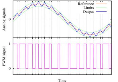
A PWM used to generate a varying analogue equivalent. Taken from Wikipedia; used under the GPL