
Programmable Industrial Hubs and Switches

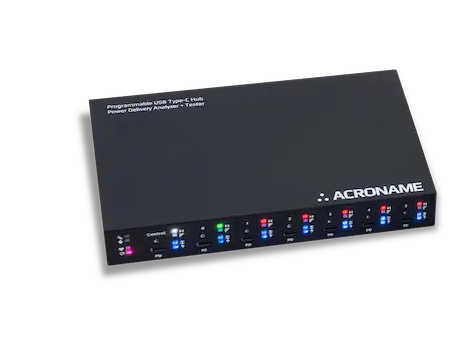
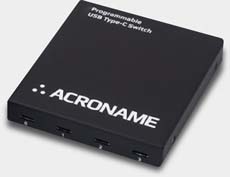
USB Type-C Hub with Power Delivery Analyzer + Tester with 8 programmable ports | USB 10Gbps
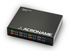
Designed for demanding industrial environments, the USBHub3+ is a USB 5Gbps Hub with 8 programmable ports
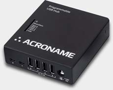
Hi-Speed USB compatible hub featuring 4 device downstream ports with standard USB Type-A connectors
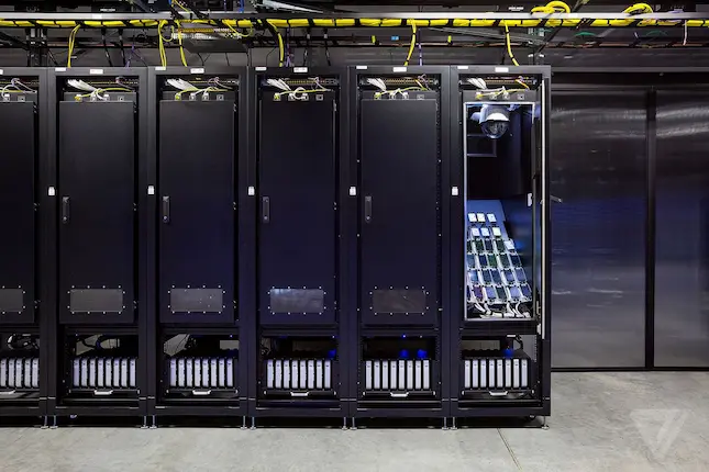
Power your Device Lab.
From repeating thousands of test cycles to withstanding lightning strikes, our hubs are proven to handle the most rigorous test protocols and environments.
Other Products
Manufacturing Test Modules
Development, deployment and scaling electronics manufacturing systems.
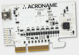
Modular Manufacturing Test Brainstem™ (MTM)
A New Paradigm In Manufacturing Test
Manufacturing Test Module (MTM) Series instrumentation from Acroname is the platform you need to free your production testers from the burdens of validation test equipment.
Benefits of MTM Brainstem

EXTENSIBLE PLATFORM
BrainStem technology complements MTM hardware as the networking and API control component of the unified test platform.

DEVELOPMENT TIME
Bringing a product to market is complicated. Test requirements always shift. Prototypes require extensive testing.

RE-USE
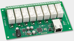
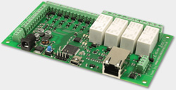
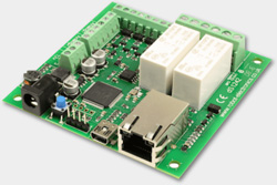
MTM modules are all off-the-shelf products. Small and consistent, you can use them like building blocks in a tester.

TESTER COMPLEXITY
With great modularity comes great simplicity. Most functional test stations have stacks of bench top equipment pushed into racks and connected with complex wire looms.