
high power loads using low-level voltage signals
A common automation system requirement is to drive or actuate high power loads using low-level voltage signals. Motors, solenoids, relays and capacitive loads can be actuated with appropriate circuitry that is only possible using small current/voltage combinations often found in embedded systems. This article attempts to illustrate and demonstrate many different mechanisms often used to provide power and/or actuate a wide range of things.
CIRCUIT PROTECTION USING FLYBACK DIODES
One thing to watch out for when designing high current drive circuits is flyback. Flyback is created when an inductive load's current path is cut off. Any piece of wire and especially the windings of a motor develop a magnetic field around them when current is passed through them. This field is left standing when the current path to ground is removed. As the magnetic field collapses, it maintains a current through the wire in the same direction that the initial current was flowing. Flyback can breakdown, damage or even ruin your circuitry. Flyback is often avoided using flyback diodes. These diodes are meant to prohibit this large spike from destroying your circuitry.
If you need to add your own flyback diodes to a circuit, make sure to use high speed diodes which can handle the demands of flyback protection. Also keep in mind that the voltage dissipated by the diodes can be higher than that of the drive circuit if a motor is turned faster as would happen when "coasting" a robot down a slope. The diode must be able to handle the same amount of current drawn when the motor is running.
RELAYS to drive currents
Relays are relatively simple interfaces often used to drive current to a wide range of systems including both DC and AC. A relay acts much like a single-pole-single-throw (SPST) switch, but instead of using a finger to change the state of the contacts, a small magnet is used. The magnet is actually an electrical coil that has a magnetic pull when energized. The magnet's pull closes or opens the switch contacts which completes the high-current circuit allowing current to flow. You may hear an audible clicking sound as the switch contacts are latching.
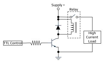
Common transistor relay driver with flyback diode
Relays have several benefits. Since a relay's electrical contacts are being physically connected together, they tend to have much lower resistance and voltage drop as compared to MOSFET and transistor based circuits. The current required to energize the magnet and close (or open) the contacts is often orders of magnitude smaller than the current flowing through the relay contacts. Relays are also self contained, so if something fails, they can be easily replaced.
The required energy to close the contacts of a relay is part of the specification for the relay being used. This current must be within the range of the logic circuit driving the relay. Many small relays are available that can be driven directly from logic currents of ~20 mA. Be sure to check your logic driver's data sheet to ensure it is capable of energizing the relay's coil.
If the relay being used has a higher current rating than the logic can provide, a transistor or MOSFET can be used to amplify the current from the logic circuit to drive the relay. Another consideration when using relays is that the coil acts as an inductor. When a wire coil has current flowing through it, a magnetic field is created. This magnetic field closes the relay's contacts. Once the current is removed from the coil, the magnetic field collapses, causing current to flow through the wire until the energy in the magnetic field is dissipated.
This can cause a damaging voltage spike back towards the logic circuit. This voltage spike is called flyback and is avoided in the above circuit with the addition of a flyback diode. This diode allows the flyback current to continue to flow in the inductor after the transistor is turned off. As the energy in the magnetic field dissipates, the current will drop, the magnetic force on the switch will reduce and the relay switch will open. This whole process can happen very quickly, but depends on the size of the coil, relay and the current flowing when the transistor is on.
MOSFETS AS SWITCHES
One often-used power switching approach for ground return loads is to use a P-Channel MOSFET as a switch. This provides a means to supply high currents with a few discrete components. An N-Channel MOSFET provides a mechanism to use TTL signals to force the P-Channel's gate close to the supply voltage when the TTL control signal is logic low. Complementarily, a TTL logic high signal creates a path to ground for the voltage divider that pulls the P-Channel's gate closer to ground and consequently turning the P-Channel MOSFET on. A zener diode between the P-Channel MOSFET's gate and source provides protection to the MOSFET if the Supply+ exceeds the allowable V_gs threshold.

Common High Side P Channel MOSFET Switch
H-BRIDGES AND THE QUARTER-BRIDGE
Directional motor control, as well as other inductive load applications can be realized by using sets of MOSFETs to manipulate the direction of current flow. A set of quarter bridges comprised of a set of MOSFETs provide current source or sinks to the load.
One may note that the diagrams show a complementary P/N Channel MOSFET combination for each quarter bridge.This approach can simplify the driving logic necessary to enable or disable the MOSFETs since the gate to source voltages are known. Often designs will utilize N-Channel MOSFETs for Q1 and Q3, but extra drive circuitry, typically with a charge pump, are required to properly drive the N-Channel.
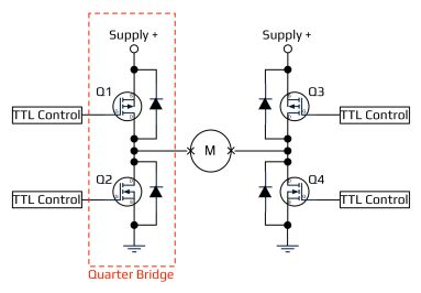
Full H-Bridge with quarter bridge highlighted
Calculated and careful combinations of which MOSFETs are enabled can make current flow through an inductive load in a prescribed manner.
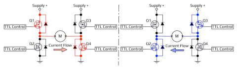
Current flow direction based on which MOSFETs are enabled
H-Bridges are very common and useful and there are canned IC solutions that combine all the discrete components into a single package. Examples of low cost chips are the SN754410NE and LM18200 made by Texas Instruments. These chips overcome many of the difficulties in designing an H-Bridge out of discrete components such as flyback diodes, voltage drop, and thermal runaway. They also combine all of the discrete components into a single package that is often much smaller than could be accomplished otherwise. Many other complete integrated chip solutions exist by almost all major chip manufacturers where many only require external MOSFETs and few other external components.
THERMAL CONSIDERATIONS
One very important consideration when designing systems is the consideration of power thermal power dissipation. It is very important to keep any electronic device within the manufacturer's thermal operation range or permanent damage to the parts may completely ruin the circuit.
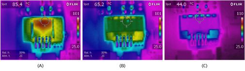
Thermal heating across a linear regulator with common configurations
The image (A) shows a linear dropout regulator (LDO) dissipating 4 watts of power continuously for 60 seconds (240 W·s) at an ambient room temperature of 20°C. The LDO's case significantly warms at the case as shown in red. The red region shows the case reaching approximately 85°C which is getting fairly warm and having a 65°C rise from ambient temperature. System operation in harsh environments around 70°C may have the case reach temperatures close to 135°C, which is above the thermal operating limit of the regulator and will have the regulator thermally shutdown. What is further interesting about this observation is the regulator is specified as a 3A up to 16V input regulator.
The second images (B) shows the effect of adding a small heat sink with thermal grease under the same test conditions. The heat dissipation from the packages matches the temperature directly around the printed circuit board yielding a 20°C drop.
The third image (C) shows the effect of adding a small heat sink and introducing a small airflow (approximately 10 CFM), which feels like a very slight breeze. The cooling effect is dramatic - showing very little negative thermal degradation effects to the loaded system.
Add New Comment