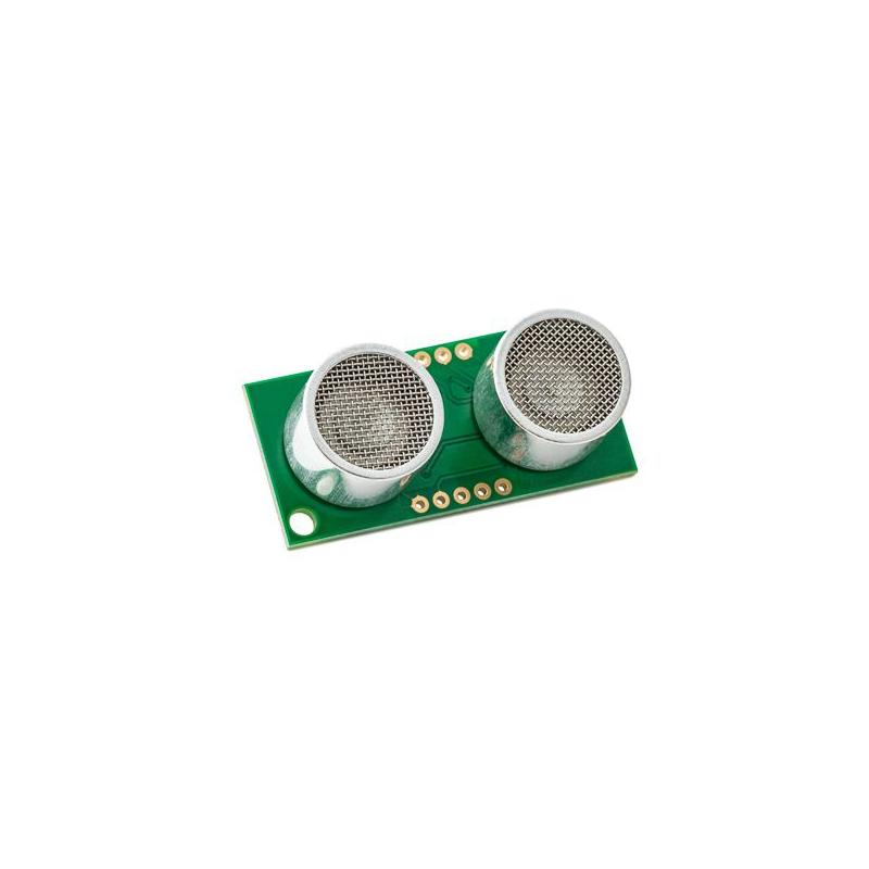
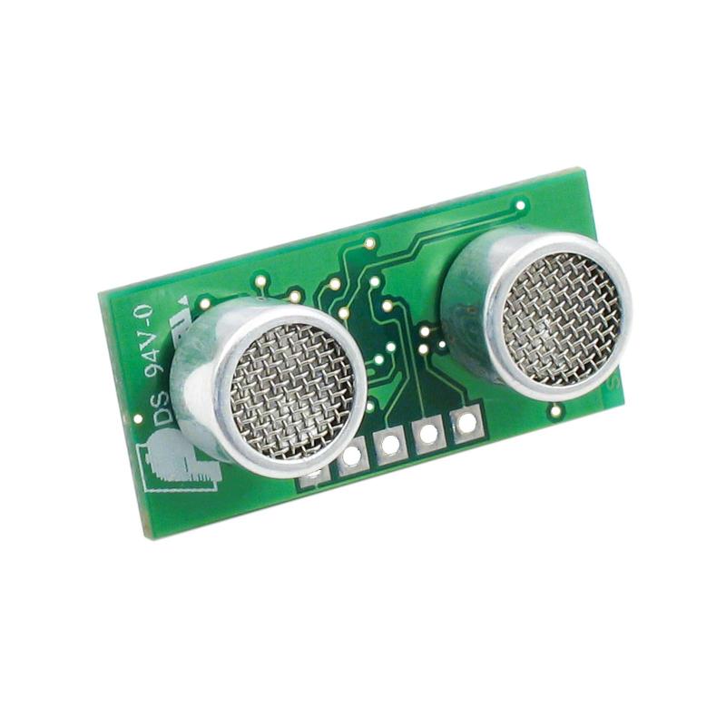
The SRF05 is a single transducer ultrasonic rangefinder with either a single pin for both trigger and echo, or separate trigger and echo pins.The SRF05 can be a drop-in replacement for the SRF04. The SRF05 returns a pulse proportional to distance that can measure from approx 1cm (0.4in) to 400cm (13ft).
This Devantech SRF05 sonar range finder is a drop-in replacement to upgrade the SRF04, able to increase range (up to a maximum of 4 meters, or 13.12 feet) while simultaneously drawing less current. The one-pin, single-wire interface makes for easy compatibility with pin-constrained systems, but it’s also backward-compatible with the SRF04. This sensor is ideal for avoiding objects in robotic applications due to its tight beam width, fast reading rate, and low power usage. Because it’s a sonar sensor, there are no concerns around ambient light, unlike infrared-type sensors. Simple fixed-point calculations yield distance approximations that can be used for calculations, robotic mapping, or path planning. Popular uses also include autonomous ground vehicles (for collision avoidance) and in alarm systems (to detect movement).
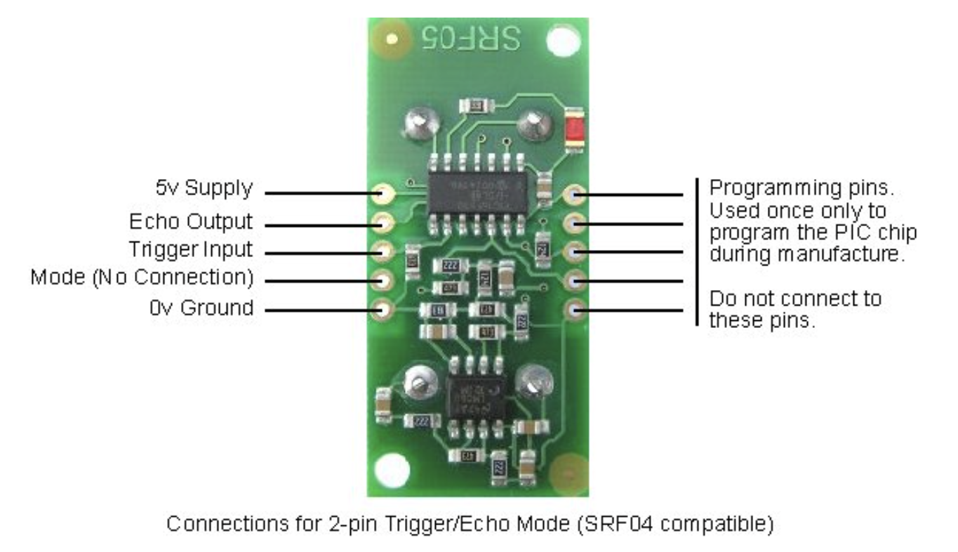
Mode 1 - SRF04 compatible - Separate Trigger and Echo
This mode uses separate trigger and echo pins, and is the simplest mode to use. All code examples for the SRF04 will work for the SRF05 in this mode. To use this mode, just leave the mode pin unconnected - the SRF05 has an internal pull up resistor on this pin.
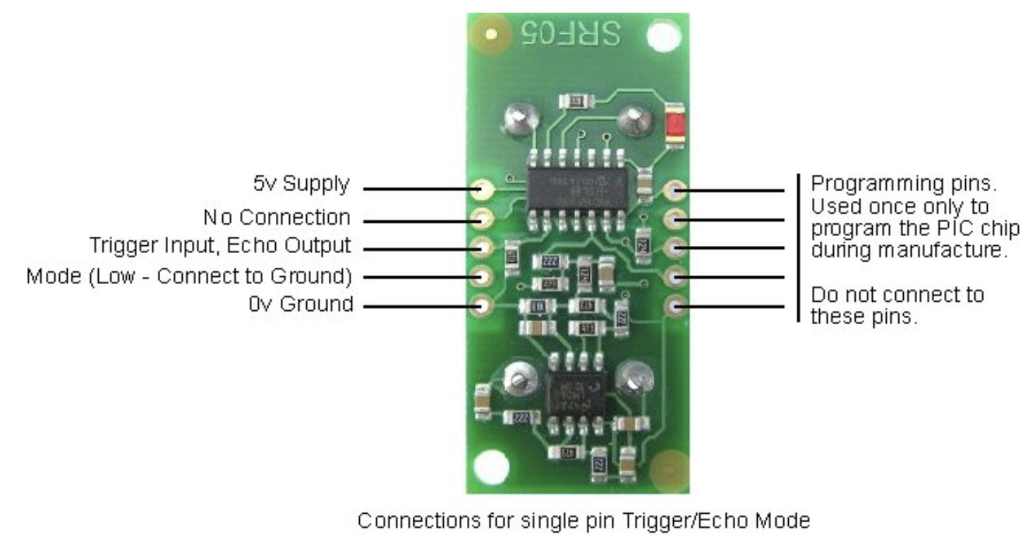
Mode 2 - Single pin for both Trigger and Echo
This mode uses a single pin for both Trigger and Echo signals, and is designed to save valuable pins on embedded controllers. To use this mode, connect the mode pin to the 0v Ground pin. The echo signal will appear on the same pin as the trigger signal. The SRF05 will not raise the echo line until 700uS after the end of the trigger signal. You have that long to turn the trigger pin around and make it an input and to have your pulse measuring code ready. The PULSIN command found on many popular controllers does this automatically.
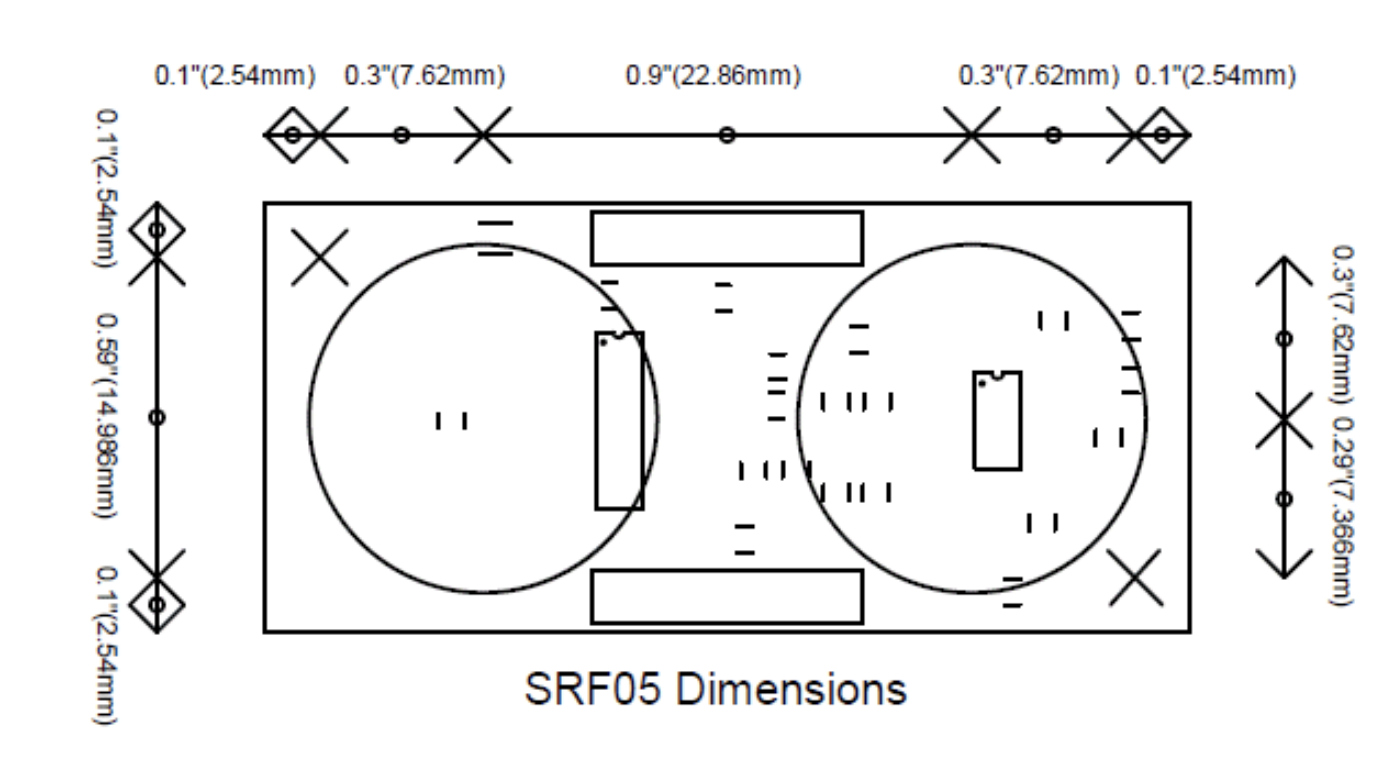
Dimensions
- Sonar distance sensor
- Single wire interface
- Lower power
- 20Hz reading rate
- Range of 3-400cm
- Small form factor
Calculating the Distance
The SRF05 timing diagrams are shown below for each mode. The distance measurement is triggered with a 10µs pulse on the trigger input. The SRF05 will send out an 8 cycle burst of ultrasound at 40kHz and raise its echo line high (or trigger line in mode 2). It then waits for an echo, and lowers the echo line when it detects one. The echo line is therefore a pulse whose width is proportional to the distance to the object. By timing the echo pulse it is possible to calculate the range. If nothing is detected then the SRF05 will lower its echo line anyway after 30ms.
If the width of the pulse is measured in µs, then dividing by 58 give a distance approximation in cm; similarly dividing by 148 gives a distance approximation in inches. µs/58=cm or µs/148=inches.
The SRF05 can be triggered approximately once every 50ms, or 20 times each second. There should be atleast 50ms between each trigger, even if the SRF05 detects a close object and the echo pulse is shorter. This is to ensure the ultrasonic signal has faded away and will not cause a false echo on the next reading.
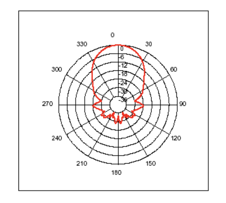
Changing beam pattern and beam width
You can't! This is a question which crops up regularly, however there is no easy way to reduce or change the beam width that I'm aware of. The beam pattern of the SRF05 is conical with the width of the beam being a function of the surface area of the transducers and is fixed. The beam pattern of the transducers used on the SRF05, taken from the manufacturers data sheet, is shown below.
| Characteristics | ||
| Voltage | 5V | |
| Current | 4mA typically | |
| Ultrasound Frequency | 40kHz | |
| Minimum Range | 3cm | |
| Maximum Range | 4m | |
| Input Trigger | 10µs minimum, TTL level pulse | |
| Echo Pulse | Positive TTL level signal, proportional to range | |
| Size | 43 x 20 x 17mm | |
| Connection Type | Digital | |
People Also Viewed

The Devantech SRF04 sonar range finder is a single-transducer ranging module with a 2-pin serial interface. With a range from 3cm to 3m (or 1.2in to 9.8ft), it’s ideal for situations that require accurate ranging information.
The Devantech SRF10 is an ultrasonic rangefinder with a I2C interface that combines a self-contained design with minimal power draw. Able to measure in both centimeters and inches, the ranging module can measure from 3cm to 600cm (1.2 inches to 19 feet).
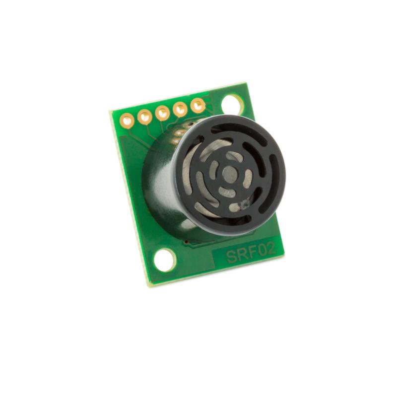
The SRF02 is a single transducer ultrasonic rangefinder in a small footprint PCB. This Devantech ultrasonic sonar ranging module has I2C and Serial interfaces with a range of 16 cm to 6 m (about 6 inches to 19 feet)
Add New Review