
ElectroMotive Force
Electromotive force (EMF) refers to the voltage generated by a spinning motor. Measuring this voltage in order to determine the rotational speed of a motor is commonly called Back-EMF since the voltage tends to "push-back" against the circuit driving current into a motor's windings. This speed indication may be used in motion control algorithms to modulate the velocity or to compute the angular distance the motor has traveled over time.
Back-EMF-based Motion Control Feedback
Typically a motor takes power in the form of voltage and current. This power is converted over time into mechanical energy in the form of rotation. With a generator, this process is simply reversed; it takes mechanical energy and converts it into electrical energy with a voltage and current. Most motors can be generators by just spinning the motor and looking for a voltage/current on the motor's windings. A simple demonstration of this effect is to wire two motors together. Spinning one motor causes the other to spin based on the current created when turning the windings of the first motor.
When using Back-EMF measurements for motion control, the concept that a motor is also a generator is exploited. The motor is run almost continually with current being driven into the windings. Occasionally, and for a very short period of time, the process is reversed. The drive circuitry stops supplying current and the windings are allowed to electrically float. The inertia in the motor system keeps it spinning and a measurement of the voltage from the spinning motor/generator is taken. This process can happen in a exceedingly short time, so it is nearly invisible to the an observer of the motor.
The voltage observed when the motor is spinning is directly proportional to its rotational velocity and the physical properties of the motor. As such, the motor's rotational velocity can be computed with no optical encoders or other forms of active feedback.
Reading rotational velocity USING BACK-EMF
Reading the rotational velocity from a motor using Back-EMF requires two alternating steps.
First, the motor is run.
Run for some period of time by providing current to the windings. This current can be supplied as a constant voltage or a pulse width modulated (PWM) motor input; the latter is the most common since it allows for the motor speed to be varied.
Second, remove the driving voltage.
Then, electrically float the windings. Electrically floating means there is no active circuit between the windings and any other source/sink. A circuit capable of measuring the voltage across the windings can then be connected or activated. The inertia in the motor and mechanical system causes the motor to continue to spin long enough to measure the voltage produced by the motor. Typically these steps are alternated at roughly 50Hz, or once every 20 milliseconds.
The time required for the motor to flip from a motor to a generator depends on the inherent capacitance and stored charge in the inductance of the motor windings. This time is typically on the order of milliseconds (1-2ms), and depends on many conditions and characteristics of the motor. Watching the process on an oscilloscope can provide insight into the time response of the motor system.
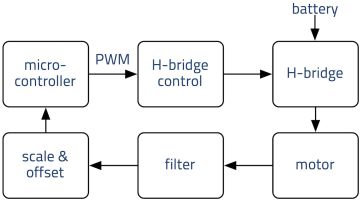
Some illustrated oscilloscope pictures are presented below to show these various steps and introduce some terminology used to control a motor using Back-EMF. These illustrations are based on an example setup where a microcontroller's logic-level PWM output is used to control an H-bridge. The microcontroller is also used to indirectly measure the Back-EMF voltage after filtering and scaling using a built-in A2D.
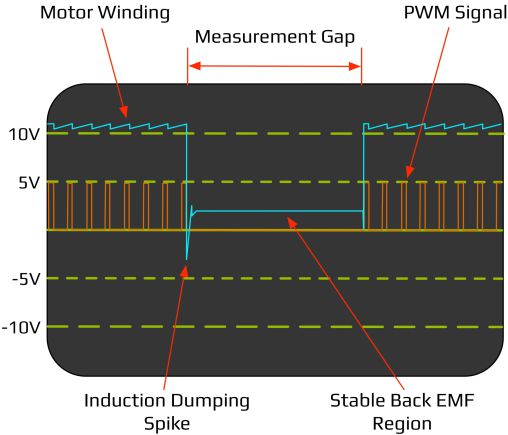
25% Simulated Duty Cycle
The diagram above illustrates how an oscilloscope might look when running a motor at 1/4 speed from a PWM drive circuit. Notice how the Back-EMF voltage stabilizes at roughly 1/4 of the PWM maximum voltage. If the Back-EMF measurement gap is too long, the motor will begin to slow down and the voltage will drop accordingly.
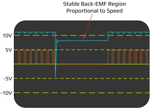
75% Simulated Duty Cycle
By increasing the PWM duty-cycle to 3/4 speed, an oscilloscope reading would appear approximately as illustrated above. This diagram is similar to the previous one, but now the stable Back-EMF signal is roughly 3/4 of the maximum motor winding drive voltage.
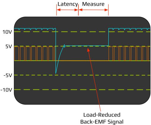
75% Simulated Duty Cycle with High Load
Finally, the diagram above illustrates the 3/4-speed case with the motor under load.
Increasing the load on the motor causes it to draw more current from the drive circuitry while it is supplying volage. The higher current in the motor windings causes a larger inductance in the windings. The inductive spike is larger in magnitude and it takes longer to stabilize to the Back-EMF region.
The duration of the inductive spike is based on the time for the system to dissipate power in the inductance and capacitance of the motor winding system. Proper tuning of the measurement latency, the time before taking the Back-EMF measurement, is important to minimize the measurement gap while allowing enough time for stable and accurate Back-EMF measurement.
challenges with BACK-EMF CIRCUITS
Designing a Back-EMF measurement circuit is challenging. The circuit needs to handle possibly large voltages from the motor and convert them into a voltage range an analog to digital (A2D) converter can handle. The circuit also needs to tolerate large inductive voltage spikes.
Further, the voltage across the motor windings invert when the motor direction changes, so the circuit needs to adjust the voltage polarity and range and create an input offset so that the neutral, not spinning, voltage output of the measurement circuit centers around a known value.
If the motor is only running in one direction, the circuit can be as simple as a resistor ladder to scale the voltage to a desired A2D input range, such as an A2D built into a microcontroller. If the motor is running bi-directionally, a more sophisticated circuit is required.
At one time, Acroname offered an H-Bridge which used a two-stage operational amplifier to manage the voltage scaling and offset of the Back-EMF measurement. Since that circuit used the LMD18200 H-Bridge driver, turning on the "brake" is used to ensure that the motor windings are floating during the Back-EMF measurement gap. Activation of the brake during a Back-EMF measurement is sometimes referred to as "auto braking".
There are as many ways to measure the voltage in a Back-EMF circuit as there are potential motor, direction and voltage combinations. The key is to ensure that the measurement is passive so it doesn't affect the motor, that it is executed when the drive circuit is not active, and that it is fast so that the motor can spend most of the time supplying mechanical force to the system.
VELOCITY MEasurement LIMITATIONS
Back-EMF velocity measurement is especially useful if it is not possible to utilize an encoder on the motor or drivetrain. High quality quadrature encoders will typically out perform any Back-EMF measurement method described here. In addition, encoders can give absolute position information whereas Back-EMF report velocity.
Position must be computed through integrating the velocity over time which can introduce significant and accumulating errors.
Another limitation of Back-EMF velocity control is that it effectively reduces the maximum duty cycle that can be employed on the motor driver, as it requires the motor to be turned off at times during the operation to facilitate measurements.
Back-EMF motion control has been employed for decades with uses in model trains, audio tape transport mechanisms and other special purpose uses. Acroname first learned of this approach to speed control while talking with Randy Sargent about work he and Bill Bailey were doing with velocity measurement for robotics. Thanks to Randy and Bill for sharing this information with the robotics community.
Add New Comment