OVERVIEW
Photoresistors are used in many applications because they either increase or decrease in resistance depending on the amount of light. A common application for photoresistors is the triggering of an event when the light passes a certain point. This example demonstrates the use of a photoresistor to toggle the User LED.
BrainStem application examples require the BrainStem Support package.
THE SETUP
There are several hardware components needed for this example:
- 40-Pin EtherStem 1.0 Module
- 40-Pin Breakout Board
- Ethernet Cable
- Photoresistor
- Resistor
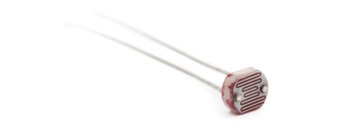
PHOTORESISTOR
A photoresistor is a sensor whose resistance varies with light intensity. Most photoresistors decrease in resistance as the light intensity increases. Typically, the resistance must be converted to a voltage so that an A2D converter can measure it. A voltage divider circuit is the easiest way to convert a resistance to a voltage.
A voltage divider is just two resistors in series connected between a voltage supply and ground. If R1 is connected to the voltage supply and R2 is connected to ground then the voltage at the junction between the two resistors is:

If R1 is the photoresistor, the voltage will increase with increasing light intensity. If R2 is the photoresistor, the voltage will decrease with increasing light intensity.
CONFIGURATION
Connect the BrainStem to the development board with a power supply connected and the Ethernet cable connecting the Stem to the host computer. Connect the Photoresistor to the 3.3V output and to the A2D pin [A2D0 for this example]. Connect a resistor in series between the Photoresistor and ground.

Detailed View
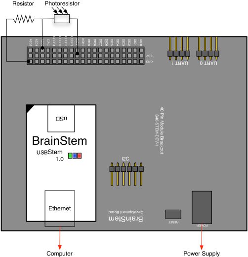
Wiring Diagram
READING ANALOG WITH REFLEX
The voltage of analog pins can be read using the Voltage entity of the Analog class. With the Voltage entity, the voltage of the analog pin can be stored in a variable that can then be compared to a threshold. Once the variable passes the threshold, the System class is used to turn the LED on using the LED entity. The Sleep entity of the System class is then used to slow the loop process.
READ A PHOTORESISTOR
#include <a40PinModule.reflex>

#define DELAY 1000000

a40PinModule stem(a40PINSTEM_MODULE);

reflex mapEnable()
{
  short bPhotoState = 0;
  char i = 0;
  short toggleVoltage = 5000;

  while (i < 100) {

    stem.analog[0].getVoltage(bPhotoState);

    if (bPhotoState < toggleVoltage) {
      stem.system.setLED(true);
    }

    else {
      stem.system.setLED(false);
    }

    stem.SYSTEM.sleep(DELAY);
    i = i+1;

  } // end of while loop
} // end of mapEnable
Line 15 - Reads voltage of analog pin 0.
Line 18 - Turns the User LED on.
Line 22 - Turns the User LED off.
Line 25 - Sleep used to slow the iterations.